Application
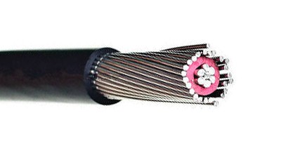
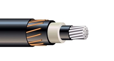
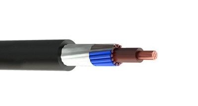
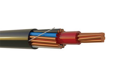
SE 型入户电缆主要用于将电力从入户引入线输送至电表底座,再从电表底座输送至配电盘。它也可用于所有允许使用 SE 型电缆的场合。SER 可在干燥或潮湿场所使用,温度不超过 90 °C,额定电压为 600 V。
Type SE, service entrance cable is primarily used to convey power from the service drop to the meter base and from the meter base to the distribution panel board
SE 型入户电缆主要用于将电力从入户引入线输送至电表底座,再从电表底座输送至配电盘。它也可用于所有允许使用 SE 型电缆的场合。SER 可在干燥或潮湿场所使用,温度不超过 90 °C,额定电压为 600 V。
• ASTM- All applicable standards • UL Standard 44 for XHHW-2 conductors • UL Standard 83 for THHN/THWN conductors • UL Standard 854 • Federal Specification A-A-59544 • National Electrical Code, NFPA 70. 2011 Edition
SE 型入户电缆主要用于将电力从入户引入线输送至电表底座,再从电表底座输送至配电盘。它也可用于所有允许使用 SE 型电缆的场合。SER 可在干燥或潮湿场所使用,温度不超过 90 °C,额定电压为 600 V。
• ASTM- B-800 and B-801 • UL Standard 83 for THHN/THWN-2 • UL Standard 44 for XHHW-2 • Federal Specification A-A-59544 • National Electrical Code/NFPA 70, 2011 Edition • RoHS
| Size/ Construction (AWG) | Stranding | Nominal O.D. (mils) | Approximate Weight per 1000' (lbs) | Allowable Ampacities+ | Standard Package | ||||
| Phase & Neutral Conductors | Equipment Ground Conductor | 60° C | 75° C | 90° C | Dwelling | ||||
| SER Copper TWO CONDUCTOR WITH BARE GROUND (FORMERLY REFERRED TO AS "THREE CONDUCTOR") | |||||||||
| 8-8-8 | 7 | – – | 586 | 231 | 40 | 50 | 55 | – – | B |
| 6-6-6 | 7 | – – | 669 | 338 | 55 | 65 | 75 | – – | B |
| 4-4-4 | 7 | – – | 764 | 498 | 70 | 85 | 95 | 100 | B |
| 3-3-3 | 7 | – – | 829 | 611 | 85 | 100 | 110 | 110 | B |
| 2-2-2 | 7 | – – | 896 | 752 | 95 | 115 | 130 | 125 | B |
| 1-1-1 | 19 | – – | 1021 | 948 | 110 | 130 | 150 | 150 | C |
| 1/0-1/0-1/0 | 19 | – – | 1114 | 1169 | 125 | 150 | 170 | 175 | C |
| 2/0-2/0-2/0 | 19 | – – | 1209 | 1444 | 145 | 175 | 195 | 200 | C |
| 3/0-3/0-3/0 | 19 | – – | 1317 | 1792 | 165 | 200 | 225 | 225 | C |
| 4/0-4/0-4/0 | 19 | – – | 1438 | 2226 | 195 | 230 | 260 | 250 | C |
| SER Copper THREE CONDUCTOR WITH BARE GROUND (FORMERLY REFERRED TO AS "FOUR CONDUCTOR") | |||||||||
| 8-8-8-8 | 7 | 7 | 645 | 286 | 40 | 50 | 55 | – – | B |
| 6-6-6-6 | 7 | 7 | 738 | 424 | 55 | 65 | 75 | – – | B |
| 4-4-4-6 | 7 | 7 | 844 | 585 | 70 | 85 | 95 | 100 | B |
| 3-3-3-5 | 7 | 7 | 910 | 719 | 85 | 100 | 110 | 110 | B |
| 2-2-2-4 | 7 | 7 | 984 | 887 | 95 | 115 | 130 | 125 | B |
| 1-1-1-3 | 19 | 7 | 1132 | 1117 | 110 | 130 | 150 | 150 | C |
| 1/0-1/0-1/0-2 | 19 | 19 | 1235 | 1382 | 125 | 150 | 170 | 175 | C |
| 2/0-2/0-2/0-1 | 19 | 19 | 1342 | 1713 | 145 | 175 | 195 | 200 | C |
| 3/0-3/0-3/0-1/0 | 19 | 19 | 1462 | 2129 | 165 | 200 | 225 | 225 | C |
| 4/0-4/0-4/0-2/0 | 19 | 19 | 1598 | 2650 | 195 | 230 | 260 | 250 | C |
| Table values reflect XHHW-2 conductors Allowable ampacities shown are for general use as specified by the National Electrical Code, 2011 Edition, section 310.15 and 240.4(D). Unless the is marked for use at higher temperaturesthe conductor ampacities shall be limited to the following per NEC 110.14(C) 60 ° C When terminated to equipment for circuits rated 100 amperes or less or marked for 14 – 1 AWG conductors. 75 ° C When terminated to equipment for circuits rated over 100 amperes or marked for conductors larger than 1 AWG . 90 ° C XHHW wet or Dry locations for ampacity adjustment purposes using NEC section 310.15 For dwelling ampacity use section 310.15(B)(7) | Package Code B- 1000' Reel C- 500' Reel | ||||||||
| Conductor | Stranding | Nominal O.D. (mils) | Approximate Weight per 1000' (lbs) | Allowable Ampacities+ | Standard Package | ||||
| Size (AWG) | Phase Conductors | Bare Ground | 60° C | 75° C | 90° C | Dwelling | |||
| SEU Copper ONE CONDUCTOR WITH A BARE CONCENTRIC GROUND (FORMALLY REFERRED TO AS "TWO CONDUCTOR") | |||||||||
| 8-8 | 7 | 8 | 400 | 144 | 40 | 50 | 55 | – – | ABC |
| 6-6 | 7 | 12 | 435 | 208 | 55 | 65 | 75 | – – | |
| 4-4 | 7 | 12 | 506 | 315 | 70 | 85 | 95 | – – | C |
| 2-2 | 7 | 15 | 580 | 485 | 95 | 115 | 130 | – – | |
| SEU Copper TWO CONDUCTOR WITH A BARE CONCENTRIC GROUND (FORMALLY REFERRED TO AS "THREE CONDUCTOR") | |||||||||
| 10-10-10 | 1 | 12 | 428 X 283 | 127 | 30 | 30 | 30 | – – | ABC |
| 8-8-8 | 7 | 8 | 587 X 380 | 211 | 40 | 50 | 60 | – – | ABC |
| 6-6-6 | 7 | 12 | 659 X 416 | 308 | 55 | 65 | 75 | – – | BCE |
| 4-4-4 | 7 | 12 | 815 X 506 | 471 | 70 | 85 | 95 | 100 | BCE |
| 3-3-3 | 7 | 12 | 883 X 548 | 583 | 85 | 100 | 110 | 110 | B |
| 2-2-2 | 7 | 15 | 994 X 578 | 718 | 95 | 115 | 130 | 125 | BD |
| 1-1-1 | 19 | 14 | 1093 X 664 | 904 | 110 | 130 | 150 | 150 | B |
| 1/0-1/0-1/0 | 19 | 18 | 1179 X 707 | 1123 | 125 | 150 | 170 | 175 | BC |
| 2/0-2/0-2/0 | 19 | 18 | 1283 X 767 | 1379 | 145 | 175 | 195 | 200 | BC |
| 3/0-3/0-3/0 | 19 | 14 | 1429 X 862 | 1712 | 165 | 200 | 225 | 225 | BD |
| 4/0-4/0-4/0 | 19 | 18 | 1541 X 918 | 2146 | 195 | 230 | 260 | 250 | BC |
| SEU Copper TWO CONDUCTOR WITH A BARE CONCENTRIC GROUND (FORMALLY REFERRED TO AS "THREE CONDUCTOR") (REDUCED NEUTRAL) | |||||||||
| 6-6-8 | 7 | 8 | 659 X 416 | 281 | 55 | 65 | 75 | – – | BC |
| 4-4-6 | 7 | 12 | 790 X 481 | 420 | 70 | 85 | 95 | 100 | BC |
| 3-3-5 | 7 | 15 | 843 X 508 | 515 | 85 | 100 | 110 | 110 | BC |
| 2-2-4 | 7 | 12 | 929 X 563 | 639 | 95 | 115 | 130 | 125 | BC |
| Table values reflect XHHW-2 conductors Allowable ampacities shown are for general use as specified by the National Electrical Code, 2011 Edition, section 310.15 and 240.4(D). Unless the is marked for use at higher temperaturesthe conductor ampacities shall be limited to the following per NEC 110.14(C) 60 ° C When terminated to equipment for circuits rated 100 amperes or less or marked for 14 – 1 AWG conductors. 75 ° C When terminated to equipment for circuits rated over 100 amperes or marked for conductors larger than 1 AWG . 90 ° C XHHW wet or Dry locations for ampacity adjustment purposes using NEC section 310.15 For dwelling ampacity use section 310.15(B)(7) | Package Code: A- 250' Coil B- 500' Reel C- 1000' Reel D- 100' Reel E- 150' Coil | ||||||||
| Conductor | Stranding* | Nominal O.D. (mils) | Allowable Ampacities+ | Approx. Net Weight per 1000' (lbs) | Standard Package | ||||
| Size/Const. AWG or kcmil | Phase Conductor & Neutral | Equipment Ground Conductor | 60° C | 75° C | 90° C | Dwelling | |||
| SER Aluminum Two Conductor With Bare Ground (Formerly referred to as "EZ-SE") | |||||||||
| 6-6-6 | 7 | – | 650 | 40 | 50 | 60 | – | 150 | B |
| 4-4-4 | 7 | – | 745 | 55 | 65 | 75 | – | 203 | B |
| 4-4-6 | 7 | – | 745 | 55 | 65 | 75 | – | 203 | B |
| 2-2-2 | 7 | – | 864 | 75 | 90 | 100 | 100 | 290 | B |
| 2-2-4 | 7 | – | 864 | 75 | 90 | 100 | 100 | 290 | B |
| 2/0-2/0-1 | 12 | – | 1140 | 115 | 135 | 150 | 150 | 527 | B |
| 2/0-2/0-2/0 | 12 | – | 1140 | 115 | 135 | 150 | 150 | 527 | B |
| 4/0-4/0-2/0 | 19 | – | 1354 | 150 | 180 | 205 | 200 | 784 | C |
| 4/0-4/0-4/0 | 19 | – | 1354 | 150 | 180 | 205 | 200 | 784 | C |
| SER Aluminum Three Conductor With Bare Ground (Formerly referred to as "Four Conductor") | |||||||||
| 8-8-8-8 | 1 | 1 | 612 | 30 | 40 | 45 | – | 136 | B |
| 6-6-6-6 | 7 | 7 | 717 | 40 | 50 | 60 | – | 196 | B |
| 4-4-4-6 | 7 | 7 | 823 | 55 | 65 | 75 | – | 252 | B |
| 2-2-2-4 | 7 | 7 | 956 | 75 | 90 | 100 | 100 | 359 | B |
| 1-1-1-3 | 8 | 7 | 1079 | 85 | 100 | 115 | 110 | 449 | C |
| 1/0-1/0-1/0-2 | 10 | 1 | 1168 | 100 | 120 | 135 | 125 | 540 | C |
| 2/0-2/0-2/0-1 | 12 | 1 | 1264 | 115 | 135 | 150 | 150 | 652 | C |
| 3/0-3/0-3/0-1/0 | 16 | 1 | 1371 | 130 | 155 | 175 | 175 | 786 | C |
| 4/0-4/0-4/0-2/0 | 19 | 1 | 1496 | 150 | 180 | 205 | 200 | 960 | C |
| 250-250-250-3/0 | 22 | 1 | 1839 | 170 | 205 | 230 | 225 | 1458 | C |
| SER Aluminum Four Conductor With Bare Ground (Formerly referred to as "Five Conductor") | |||||||||
| 2-2-2-2-4 | 6 | 7 | 1059 | 75 | 90 | 100 | 100 | 452 | B 5 |
| 2/0-2/0-2/0-2/0-1 | 12 | 1 | 1404 | 115 | 135 | 150 | 150 | 827 | C |
| 4/0-4/0-4/0-4/0-2/0 | 19 | 1 | 1672 | 150 | 180 | 205 | 200 | 1228 | C |
| 50-250-250-250-3/0 | 22 | 1 | 1847 | 170 | 205 | 230 | 225 | C | |
| SEU Aluminum Two Conductor With Bare Concentric Ground (Formerly referred to as "Three Conductor") | |||||||||
| 6-6-6 | 7 | 8 | 430 X 687 | 40 | 50 | 60 | – | 145 | H |
| 4-4-4 | 7 | 12 | 499 X 800 | 55 | 65 | 75 | – | 198 | I |
| 4-4-6 | 7 | 15 | 474 X 775 | 55 | 65 | 75 | – | 181 | I |
| 2-2-2 | 7 | 14 | 569 X 925 | 75 | 90 | 100 | 100 | 283 | I |
| 2-2-4 | 7 | 18 | 554 X 910 | 75 | 90 | 100 | 100 | 259 | I |
| 2/0-2/0-2/0 | 18 | 18 | 736 X 1221 | 115 | 135 | 150 | 150 | 514 | CJ |
| 2/0-2/0-1 | 18 | 14 | 720 X 1205 | 115 | 135 | 150 | 150 | 468 | CJ |
| 4/0-4/0-4/0 | 18 | 18 | 878 X 1462 | 150 | 180 | 205 | 205 | 765 | CL |
| 4/0-4/0-2/0 | 18 | 18 | 835 X 1419 | 150 | 180 | 205 | 205 | 691 | CL |
| Table values reflect XHHW-2 conductors. +Allowable Ampacities: Allowable ampacities shown are for general use as specified by the National Electrical Code, 2011 Edition, Section 310.15. 60° C – When terminated to equipment for circuits rated 100 amperes or less or marked for 14 through 1 AWG conductors. See NEC Article 338.10(B)(4). 75° C – When terminated to equipment for circuits rated over 100 amperes or marked for conductors larger than 1 AWG. May not apply, see NEC Article | |||||||||
| 338.10(B)(4). | |||||||||
| 90° C – Wet or dry locations. For ampacity derating purposes. | |||||||||
| Dwelling – For units, conductors shall be permitted at listed ampacities as 120/240-volt, 3-wire, single-phase services and feeders per NEC Article 310.15. | |||||||||
| *For compact-stranded construction, the number of wires, as permitted by UL Standard 83, UL Standard 854, and ASTM B-801, may be reduced as follows: | |||||||||
| 19-Wire Constructions – 18 Wires Minimum | |||||||||
Scroll horizontally to review complete specification columns.
Request Full TDSSE 型入户电缆主要用于将电力从入户引入线输送至电表底座,再从电表底座输送至配电盘。它也可用于所有允许使用 SE 型电缆的场合。SER 可在干燥或潮湿场所使用,温度不超过 90 °C,额定电压为 600 V。
Product image and technical reference.